Friday 31 March 2017

INFORMATION STORAGE DEVICES

Who Many Types Of Information Storage Devices?

A storage device designed to store information in computer. Storage devices work on different principles using electronics. magnetism and laser technology. There Types of Information storage devices are shown bellow.
  • Primary Memory
  • Secondary Memory
  • Audio And Video Cassettes
  • Magnetic Disks
  • Hard Disk
  • Compact Disk (CDs)
  • Flash Driver

Primary Memory

It is based on electronics and consist of Integrated Circuits (ICs). It consist of two parts; Read Only Memory (ROM), which starts the computer and Random Access Memory (RAM), which is used in computer as temporary memory. RAM vanished when the computer is switched Off.

Secondary Memory

The data storage devices are generally the secondary memory of the computer. It is used to store the data permanently in the computer. When we open program data is moved from the secondary storage into the primary storage. The secondary storage devices are audio - video cassettes and hard disk etc.

Audio And Video Cassettes

 These devices are based on magnetism. Audio cassettes consist of a tape of magnetic material on which sound is recorded in a particular pattern of a magnetic field as shown in fig bellow. For the purpose, microphone changes sound waves in to electric pulses, which are amplified by the amplifier. Magnetic tape is moved across the head of audio cassettes recorded which is in fact an electromagnet. 

Thus magnetic type is magnetized in a particular pattern according to raising or falls of current. In this way sound is stored in a specific magnetic pattern on this tape.
To produced the sound again, The tape is moved past the play back head. changes in the magnetic fields on the tape induce alternating current signals in the coil wound on the head. These signals are amplified and sent to the loud speakers which reproduced the recorded sound.

Magnetic Disks

 There are different types of magnetic disks coated with the layer of some magnetic materials. The read or write head of disk are similar to the record replay head on a tape recorder. It magnetizes part of the surface to record information. The difference is that a disk is digital medium - binary number are written or read. A floppy disk is a small magnetite sensitive, flexible plastic wafer housed in a plastic case. It is costed with a cassettes and video tapes. 


Floppies are inexpensive, convenient, and reliable, but they lack the storage capacity and drive speed for many large jobs. Data stored on floppy disks is also subjected to loss as  a result of stray magnetic fields. As far as floppy disks are contacted, they are reliable only for short - term storage and cannot be used longer and no attempts should be made to save the data for a longer period. As the magnetic field weaken the data will also be lost.

Hard Disk

 Most users are relay on the hard disk as there primary storage devices. A hard disk is a rigid, magnetically sensitive disk that spin rapidly and continuously in side the computer. chassis or in separate box connected to the computer housing. This type of hard disk is never removed by the user. A typical hard disk consist of several platters, each accessed via read or write head on a movable arm.

Compact Disc (CD's)

 This is based on laser technology. It is a molded plastic disc on which digital data is stored in the form of microscopic reflecting and non reflecting spots which are called "Pits" and "Lands" retrospective. Pits are the spiral tracks encoded on the top surface of CD and land are the areas between pits. A fine laser beam scans the surface of the rotating disk to read the data.Pits and lands reflect different amount of the laser light failing on the surface of the CD. This pattern of different amounts of the light reflected by the pits and the lands is converted into binary data. The presence of pits indicates '1' and absence of pits indicates '0'.
A CD can store over 680 megabyte of computer data. A DVD, the same size as traditional CD, is able to store up-to  17 gigabits of data.

Flash Driver

It is also an electronic based device and consist of data storage ICs. A flash drive is a small storage device that can be used to transports files from one computer to another computer. Many of these devices carries your all homework for an entire Year! we can keep one on a key chain, carry it around our neck, or attached it to our book bag.

A flash drive is easy to use. One we have created a paper or other work we can simply plug our Flash drive into our USB port, We must make a backup of our created paper or project on our flash drive and save it separate fro our computer. A flash drive also come in handy if you are able to print out homework at school or Office.You can write a paper at home, save it to your flash drive and then plug the drive into a USB port on a school or office computer.

Thursday 30 March 2017

TRANSMISSION OF RADIO WAVES THROUGH SPACE

Explanation Of Transmission Of Radio Waves Through Space

TRANSMISSION OF RADIO WAVES: Electrical signals respectively information from a  microphone,  a TV camera, or a computer can be sent from one place to another place using either cables or radio waves. Information in the forms of audio frequency (AF) signals may be transmitted directly by the cable. However, in order to send information over a long distance, it has to be superimposed in electromagnetic waves.

radio transmission and receiving system

Sound waves produced at the radio station are changed into electrical signals through microphone. These electric signals are then fed into the transmission antenna that consists of two metal roads. Signal falling on the transmission antenna oscillate the charges which which then emit these electrical signals in the form of electromagnetic radio waves.

At the receiving end, the receiver selects and amplifies the modulated signal. The demodulate  then extract the information signals and deliver it to be the receptor.Radio transmission and Receiving system is shown above in Fig.

Fax Machine

 Facsimile's or Fax machine are must for many business around the World. A fax machine basically scans a page convert its text and graphic into electronic signals and transmit it to another fax machine through telephone line. The reviving machine convert the signal and use a printer  (usually built in) to create the copy of the message that was sent.

Cell Phone

 Radio technology is applied in mobile phone. It is a type of radio having two way communication. A cell phone a carries a radio transmitter and receiver inside it. It sends and receives the message in the form of radio waves. Cell phone networking system consist of Cells and Base Station (BSS) and Mobile Switching Center (MSC). A base station is wireless communication station set up at a particular geographical location. The geographical area converted by a single base station is known as Cell.

The group of cells forms a cluster. All BSS with in a cluster are connected to To MSC using land lines. The MSC stores information about the subscriber located within the cluster and is responsible for directions calls to them. When a caller calls another cell phone, sound waves of the caller are converted into radio radio waves signal. This radio signal of particular frequency is sent to the local base station of the caller where the signal is assigned a specific radio frequency. This signal is then sent to the base station of the receivers through the receivers. Mobile receiving again changes the radio waves into sounds.

Photo Phone

 Modern version of photos or video phones is shown bellow. Contrary to a common telephone, users can see the pitcher of each other. By using the photos and phone number of our friends or family member on this telephone, we can call them by pressing the pad with their or friends on photo phone with the physical appearances of each other.

Wednesday 29 March 2017

ANALOGUE AND DIGITAL ELECTRONICS

What Is Analogue and Digital Electronics?

ANALOGUE AND DIGITAL ELECTRONICS: The qualities whose values vary continuously or remain constant are known as analogue qualities. For example, the temperature of air varies in continuous fashion during 24 hours of a day. If we plot a graph between time and temperature recorded at different times, we get a graph as shown bellow. This graph shows that temperature varies continuously with time. Therefore, we say that temperature is an analogue quantity. Similarly, time, pressure, distance, etc. are analogue quantities.

ANALOGUE AND DIGITAL ELECTRONICS

The batch of electrons consisting of circuit which process analogue quantities is called analogue electronics. For instance, the public address system is an analogue system in which the microphones convert sound into a continuously varying electric potential. This potential is an analogue signal which is fed into an amplifier. Amplifier is an analogue circuit which amplifies the signal without changing its shape to such an extant that it can operate a loudspeaker. In this way loud sound is produced by the speaker. Radios, television, and telephones are a few common devises that process analogue signals. 

The quantities whose values vary in non-continuous manner is called digital quantities. Digital variation of analogues signal is shown above in fig. Digital quantities are expressed in the forms of digits or numbers. The branches of electronics which deals with digital quantities is called digital electronics.  Digital electronics uses only two digits '0' and '1' and the whole data is provided in binary form due to which processing of data becomes easy.

A continuously varying signals are called an analogue signal. For maximum value of +5 V  and the minimum value is -5 V is an analogue signal. A signal that can have only two directional value is called digital signals. For example a voltages with square wave form is a digital signal. This signal has only two values i.e, +5 V and 0 V. The high voltages is +5 V and the low voltages is 0 V. It can be seen that digital signals provides the data by a maximum and a minimum voltages level. The changes occurring in the digital signal are not continuous. For quality a long period, the uses of digital electronics was limited to computers only but now a days its application is very wide spread.


Modern telephone system, radar system, naval and other system of military importance, devises to control the operation of the industrial machines, medical equipment and many household appliances are using digital technology.

In our daily life, the quantities that we perceive by our scenes are usually analogue quantities which cannot be processed by digital circuit. To overcome this problem, a special circuit has been designed which converts it to binary form the analogue signal into a digital one in the form of digits in binary form. This circuit is known as Analogue to Digital Converter (ADC). This binary output is then processed by a computer which also gives output in digital form. The output of the computer is again converted into an analogue form by a circuit known as Digital to Analogue Converter. (DAC). As the output DAC is an analogue signal, it can be readily sensed by us. Thus, electronic system used at present consist of both analogue and digital type circuits.

Tuesday 28 March 2017

CATHODE-RAY OSCILLOSCOPE (C.R.O)

What is Cathode-Ray Oscilloscope?

The cathode ray oscilloscope is an instrument which is used to display the magnitudes of changing electric current or potentials. The information is displayed on the screen of a "Cathode Ray Tube". This screen appears as a circular or rectangular window usually with a centimeter graph superimposed on it.For example, the pitcher tube in our TV set and display terminal of most computers are cathode-ray tubes.


The cathode-ray tube oscilloscope (C.R.O) consist of following component :
  • The electronic gun with control grid
  • The deflecting plates 
  • A fluorescent screen

The Electronic Gun

The electronic gun consist of an electrons source which is an electrically heated cathode that ejects electrons. Electron gun also has an electrode called grid "G" for controlling the flow of electrons in the beam. The grid is connected to a negative potential. The more negative this potential, the more electrons will be repulsed from the matrix and consequently less will achieve the anode and the screen. The number of electrons reaching the screen determines the brightness of the screen. Hence, the negative capability of the network can be utilized as a lights up control. The anode is connected to positive potential and hence is used to accelerate the electrons. The electrons are engaged into a fine bar as they go through the anode.


The Deflecting plates

After leaving the electron gun, the electron beam passes between a pair of horizontal plates. A potential difference applied between these plates deflects the beam in vertical plane. This pairs of plates provides the Y-axis or vertical movement of the spot on the screen. A pair of vertical plates provide the X-axis or horizontal movement of the spot on the screen.


The Fluorescent Screen

 The screen of the cathode-ray tube consist of the thin layer of phosphor, which is a material that gives light as a result of bombardment by fast moving electrons.

The C.R.O is used in many field of science, displaying waveform, measuring voltages, range finding (as in radar), echo-sounding (to find the depth of sea-beats.

Monday 27 March 2017

MUTUAL INDUCTION | TRANSFORMER

What is Mutual Induction?

 MUTUAL INDUCTION: The phenomena of production of induced current in a coil due to change of current in a neighboring coil is called Mutual Induction.

 Suppose a system of two coil A and B placed close to each other. The coil A is connected to a battery and a switch, while a sensitive galvanometer is connected to the coil B. We observes as soon as the switch of a coil A is closed, the galvanometer shows a momentary deflection.

MUTUAL INDUCTION

 Similarly when the switch is opened, the galvanometer again shows a deflection but this time it's direction is opposite to that of the previous case.

We can explain these observations using Faraday's Law of electromagnetic induction. When the switch of coil A is closed, a current begin to flow in the coil due to which magnetic field is developed across the coil. Some of the magnetic lines of force this field start passing through the coil B. Since current is changing in the coil A, hence number of magnetic lines of force across the coil B also change due to which the current induced in the coil A becomes steady, number of magnetic lines of force across the coil A also becomes constant. Therefore, there is no more change in number of magnetic lines of force through the coil B due to which induced current in coil B reduces to zero.

Similarly when the switch of the coil A is opened, the flow of current through it stop and its magnetic field reaches to zero. The number of magnetic lines of force through the coil B decreases to zero due to which current is again induced in it but in opposite direction to that in the previous case.

 What is Transformer?

 The transformer is a practical application of mutual induction Transformer is used to increase or decrease AC voltages. Usage of transformer is common because they change voltages with relative little loos of energy. In fact, many of the devises in our homes, such as game systems, printers and stereos use transformer for their working.

Working of Transformer

A transformer has two coils, electrically insulated from each other, but wound around the same iron core. One coil is called Primary Coil. The other one is called Secondary Coil. Number of turns on the primary and the secondary coil are represented By Np and Ns respectively.


When primary coil is connected to a source of AC voltage, the changing current creates a changing in a magnetic field, which is carried through the core to the secondary coil.In the secondary coil, the changing field induces an alternating e.m.f.

The e.m.f. induced in the secondary coil, called the secondary Voltages Vs is proportional to the primary voltages Vp. The secondary voltages also depends on the ratio of the number of turns on the secondary coil to the number of turns on the primary coil, as shown by the following expression:
     
                                                           Vs / Vp = Ns / Np


If the secondary voltages is large then the primary voltages, the transformer is called Step-up Transformer. If the secondary voltage is smaller than the primary voltage, the transformer is called Step-up Transformer. In an ideal transformer, the electric power delivered to the secondary circuit is equal to the power supplied to the primary circuit.
        
                                                           Pp = Ps
                                                       Vp Ip = Vs Is


Sunday 26 March 2017

ELECTOR MAGNETIC INDUCTION

What is Electromagnetic Induction?

 ELECTOR MAGNETIC INDUCTION: Hans christen Oersted and Ampere discover That an electric current through a conductor produces that an electric current through a conductor produces a magnetic field around it. Michael Faraday thought that the revers must be true; that a magnetic field produced an electric current. Faraday found that he could in induced electric current by moving a wire through magnetic field. In the same year, Joseph Henry also showed that a changing magnetic field could produced Electric current. Now we shall discuses Faraday's experiments for the production of e.m.f. the magnetic field.
The Strength of Magnetic Field is defined as the number of magnetic lines of force passing through any surface. The number of lines of force is maximum when the surface is held perpendicular to the magnetic lines of force. That is known as Maximum Strength of Magnetic Field.

It will be minimum when surface is held parallel to the magnetic lines of force. That is known as Minimum Strength of Magnetic Field. If we placed a coil in a magnetic field of a bar magnet, some of the magnetic lines of forces pass through it. If the coil is far a way from the magnet, only a few lines of forces will pass through the coil. However, if the coil is close to the magnet, a large number of lines of forces pass through it.

This means that we can change the number of magnetic lines of force through a coil by moving it in the magnetic field. This change in a magnetic field lines will induced an e.m.f in the coil. This is a basic principle of the production of electricity. 

variation of magnetic field lines of force through a coil placed at different distances from the magnet


It implies that an electric current is generated in a wire only when the wire cuts magnetic field lines. This induced current is generated by the induced e.m.f. in the circuit. Faraday found that to generate current, either the conductor must move through a magnetic field or a magnetic field must change across the conductor. Thus,

The process of generating an induced current in a circuit by changing the numbers of magnetic lines of force passing through it  is called  Electromagnetic Induction.


When there is a relative motion between the coil and the magnet. This phenomena in which an e.m.f. is induced due to the relative motion between the coil and the magnet is called electromagnetic induction.

The values of induced e.m.f. in a circuit is directly  proportional to the rate of change of number of magnetic lines of force through it.
This is called the Faraday's Law of Electromagnetic Induction.

Factors Affecting Induced E.M.F

 The magnitude of induced e.m.f. in a circuit depends on the following factors:
  • Speed of relative motion of the coil and the magnet
  • Number of turns of the Coil

Saturday 25 March 2017

DIRECT CURRENT (D.C) MOTORS | ALTERNATING CURRENT (A.C) GENERATOR

D.C Motor

DIRECT CURRENT (D.C) MOTORS: As we can see bellow that the coil placed in a magnet cannot rotate more than 90 degree. The forces push the PQ side of the coil up and the RS side of the loop down until the loop reaches the vertical position. In this situation, plan of the loop is perpendicular to the magnetic field and the net force on the coil is zero. So the loop will not continue to turn because the forces are still up and down hence balanced.

working principle of direct current motor

How can we make this coil to rotate continuously. it can be done by reversing the direction of the current just as the coil reaches its vertical position. This reversal of current will allow to rotate the coil continuously. To the reverse direction of the current, the connection of the coil made through an arrangement of brushes and ring that is split into halves, called a Split Ring Commutator. Brushes, which are usually pieces of graphite, make contact with the commutator and allow current to flow in the loop. As the loop rotates, so does the commutator. The split ring is arranged so each half of the commutator change brushes just as the coil reaches the vertical position. Changing brushes revers the current in the loop.

As a result, the direction of the force on each side of the coil is reversed and it continue to rotate. This process repeat at each half-turn, causing coil to rotate in the magnetic field continuously. The result is an electric motor, which is a device that convert electric energy in rotational kinetic energy.

In a practical electrical motor, the coil called the armature, is made of many loops mounted on a shaft or axle. The magnetic field is produced either by permanent magnets or by elector magnates called a field coil. The torque on the armature and as a result the speed of the motor is controlled by the varying the current through the motor.
The total force acting on the armature can be increased by
  • Increasing the number of turns of the coil.
  • increasing the current in the coil.
  • increasing the current in the magnetic field.
  • increasing the area of the coil.

A.C Generator

 ALTERNATING CURRENT (A.C) GENERATOR: If a coil is rotated in a magnetic field, a current will be induced in the coil. The strength of induced current depend upon the number of magnetic lines of force passing through the coil. The number of the lines of magnetic force passing through the coil will be maximum when the plane of the coil is perpendicular to the liens of magnetic force. The numbers of the liens of magnetic force will be zero when plane of the coil is parallel to the line of force. Thus, a coil rotates in a magnetic field, the induced current in it continuously changes from maximum to minimum value and so on. This is a basic principle of which an A.C generator work.


The armature is to be arranged so that it can rotate freely in the magnetic field. As armature turns, the wire loop cut through the magnetic field liens and induced e.m.f. will be produced. The e.m.f. developed by the generator depends on the length of the wire rotating in the field. Increasing the number of loops in the armature, increases the wire length, there by increasing the induced e.m.f

Current from Generator 

When a generator is connected in a closed circuit, the induced e.m.f. generates an electric current. As the loop rotates the strength the and the direction of the current changes as shown in Fig Bellow.When the plane of will is perpendicular to field, the number of lines of magnetic force passing through it is maximum. But the change in the number of lines through the coil is minimum. So e.m.f. induced minimum.

The current is minimum when the plane of the loop is perpendicular to the magnetic field; that is, when the loop is in vertical position. As the loop rotates from the vertical to the horizontal position, it cuts through large magnetic field liens per unit of times, thus the e.m.f. and the current increase.

 When the loop is in the horizontal position, the plane of the loop becomes parallel to the field, so the e.m.f. and the current reaches its maximum value. As the loop continue to turn, the segment that was moving up begins to move down and reverse the direction of the e.m.f. and the current in the loop. This changes in a direction take place each time the loop turns through 80 degree. Thus, the e.m.f and the current changes smoothly from zero to some maximum value and back to zero value during each half turns of the loop.

Friday 24 March 2017

FORCE ON A CURRENT | TURNING EFFECTS ON A CURRENT

Force on a current - Carrying Conductor Placed In A Magnetic Field

 FORCE ON A CURRENT: We know that electric current produces a magnetic field similar to that of permanent magnet. Since a magnetic field exerts force on a permanent magnet, it implies that current - carrying wire should also experience a force when placed in a magnetic field.

The force on a wire in magnetic field can be demonstrated using the arrangement as shown above. A battery produces current in a wire placed inside the magnetic field of a permanent magnet. Current-carrying wire produces it's own magnetic field which interacts with the field of the magnet. As a result, a force is exerted on a wire. Depending on the direction of the current, the force on the wire wither pushes or pulls it toward as right or toward left.

Michael Faraday discover that the force on the wire is at right angles to both the direction of the magnetic field and direction of the current. The force is increased if

  • The current in the wire is increased.
  • Strength of the magnetic field is increased.
  • The length of the wire inside the magnetic field is increased.

Determining the direction of force

 Faraday's description of the force on a current - carrying wire does not completely specify the direction of the force because the force can be toward left or toward right. The direction of the force on a current - carrying wire in a magnetic field can be found by using Fleming's left hand rule started as:

Stretch the thumb, forefinger and middle finger of the left hand mutually perpendicular to each other. If the forefinger points in the direction of the magnetic field, the middle finger in the direction of the current, then thumb would indicate the direction of the force acting on the conductor.


The force acting on the conductor is at right angles to both the directions of current and magnetic field according to Fleming's left hand rule.

Turning Effects on a Current - Carrying Coil in a Magnetic Field 

 If rather than a straight conductor, we set a current - conveying circle inside the attractive field, the circle will pivot because of the torque following up on the loop . This is also the working principle electric motors. Consider a rectangular coil of wire with sides PQ and RS, lying perpendicular to the field, placed between the two poles of a permanent magnet. Now if the ends of the coil are connected with the negative and positive terminal of the battery, a current would start flowing through the coil. The current passing through the loop enters from end of the loop and leave from the other end.

a current carrying coil in a magnetic field


Now apply Fleming's Left Hand Rule to each side of the coil. We can see that on PQ side of the loop face acts upward, while on the RS side of the loop face acts downward. It is because of the direction of current through the two sides of the loop facing the two poles in at right angles to the field but opposite to each other. The two forces are equal in magnitude but opposite in a direction from a couple. The subsequent torque because of this couple pivots the circle, and the size of the torque acting on the up and up is corresponding to the greatness of the present going through the circle. If we increase the number of the loops, the turning effects is also increased. This is the principle of Electronic Motors.

Thursday 23 March 2017

SAFE USE OF ELECTRICITY IN HOMES | FUSE | CIRCUIT BREAKER | EARTH WIRE

Safe Use Of Electricity In Homes

SAFE USE OF ELECTRICITY IN HOMES: In order to protect persons, devises and property from the hazards of electricity there is need of extensive in safety measure in house hold electricity. Take much care to use fuse and circuit breaker in an electric circuit as safety devices. They prevent circuit overloads that can occur when too many appliances are turned ON at the same time or when short circuit is occur in one appliances.

Fuse

Fuse is safety device that is connected in series with the live-wire  in the circuit to protect the equipment when excess current flows. It is short and thin piece of metal wire that melts when large amount of current flow through it. If a large, unsafe current passes through the circuit, the fuse melts and breaks the circuit before the wires becomes very hot and cause fire.
Fuses are normally rates as 5A, 10A, 13A, 30A, etc. Different types of fuses are shown below.


Following safety measure should be taken while using fuses in household electric circuits:
(i) Fuses to be used should have slightly more rating than the current which the electric appliances will draw under normal conditions. For examples, for light circuit choose 5A fuse as the current drawn by each lamps very small (about 0.4 A for a 100 W lamp). In such circuit, 10 lamps of 100 W can be calculated by using the formula P = VI

(ii) Fuses should be connected in the live-Wire so that the appliances will not be operate after the fuse has blown.

(iii) Switch OFF the main before changing any fuse.

Circuit Breaker

 The circuit breaker act as a safety device in the same way as a fuse. It disconnected the supply automatically if current exceed the normal value. It disconnected the supply automatically if current exceed the normal value. When the normal values current passes through the live-wire the electromagnet is not strong enough to separates the contact. If something goes wrong with the appliances and large current flow through the live-wire, the electromagnet will attract the iron strip to separate the contacts and break the circuit.The spring then keeps the contacts apart. After the fault is  repaired, the contacts can then pushed back through by pressing a button on the outside of circuit breaker box.

 Earth Wire 

 Sometimes, even the fuse cannot captured the high currents coming from the live wire into the house hold appliances.  Earthing further protects the user from electric shock by connecting the metal casing of the appliances to Earth (a wired connection through the bare ground). Many electrical appliances have metal cases, including cookers, washing machine and refrigerators. The earth wire provides the safe route for the current to flow through, if the live wire touches the casing. We will get an electric shook if the live wire inside an appliances comes loose and touch the metal casing.

however, earth circuit is connected to the metal casing, so the current goes through the earth wire instead of passing through our body and causing an electric shock. A strong current passes through earth wire because it has very low resistance. This break the fuse and disconnects the appliances.

Wednesday 22 March 2017

ELECTRICAL ENERGY | JOULE'S LAW | ELECTRIC POWER

Electrical Energy And Joule's Law

   ELECTRICAL ENERGY: Turbine runs generator to produced electrical energy when water falls on it from higher gravitational potential to lower  gravitational potential. Similarly, when charge moves from a higher electrical potential to a lower potential, it delivers electric current. Thus, the process during which charges continuously move from higher potential to a lower potential, becomes a continuous sources of electrical energy.

Consider two points of potential difference of V volts. if one coulomb of charge passes between these points; the amount of energy delivers by the charge would be V joule. Hence, when Q coulomb of charges flows between these two points, then we will get QV joules of energy. If we represent this energy by W, then
Electrical energy supplied by Q charge W = QV joules .........................(i)
Now current, when charges Q flows in time t, is defined as:

         
                                      I = Q / t
      Or
                                     Q = It  ......................................(ii)

So the energy supplied by the charge Q in second  = W = V . I  .t ..................(iii)
This electrical energy can be converted into heat and other forms in the circuit.
From Ohm's law, we have V = IR
So the energy supplied by the Q charges is W = I . I . R . t   .............(iv)
Know The equation Becomes
                                              W= V . V . t / R


This Equation is called Joule's law, stated as:

The amount of heat generator in a resistance due to flow of charges is equal to the product of square of current I, Resistance R and the time duration t.

This energy can be utilized for different useful purpose. For example, bulb converts this energy into light, heat and heater and iron into heat, and fans into mechanical energy. Usually, this energy appears as heat in the resistance. This is the reason that we get heat in the resistance. This is the reason that we can get heat when current passes through heater.

Joule's Law


Electric Power

 The amount of energy supplied by current in unit time is known as Electric Power.

Hence power P can be determined by the formula 
                             Electric Power P = Electric Energy / Time = W/ T

Where W is the electrical energy given by 
                                  W = QV

Therefore, above equation becomes

Electric Power   P = QV / t = IV = I . I . R

When current I passes through a resistor R, the electric power that generators heat in the resistance is give by I . I . R.  The unit of electrical power is watt which is equal to one joule per second (1 j / s). It is represented by the symbol W. Electric bulb is commonly used in houses consumed 25 W, 40 W, 60 W, 75 W and 100 W of electric power.

Tuesday 21 March 2017

Conductor | Insulator | Combination of Resistors

CONDUCTORS

  Why do we always use metal wire for conduction of electricity?
Conductor: Because, they are good conductor of electricity and offer less resistance to the flow of current. But how can they conduct with much ease? Metal like silver and copper have overabundance of free electrons which are not held firmly with a particulars of metal. These free electrons moves randomly in all direction insides of metals When we apply external electric field these electrons can easily move in specific direction. This free moment of free electrons in particular direction under the influence of external field causes the flow of current in metal wires. The resistance of conductor increase in temperature. This is due to increase in the number of collision of electrons with themselves and with the atoms of the metals.


INSULATOR

 Insulator: All materials contain electrons. The electrons in insulator, like rubber, however, are not free to move. They are tightly bound inside atoms. Hence, current cannot flow through an insulator because there are not free electrons for the flow of current. Insulator have very large value of resistance. Insulator can easily charged by friction and the induced charged remains static on their surface. Other example of insulators are glass, wood, plastics, fur, silk, etc.

COMBINATION OF RESISTANCE

 Resistance can be connected in two ways.
(i) Series Combination
(ii) Parallel Combination 

(i) Series Combination

  In series combination, resistors are connected end to end and electric current has a single path through the circuit. This means that the current passing through each resistor is the same.


Equivalent Resistance of Series Circuit 

 The total voltages in a series circuit dividing among the individual resistors so the sum of the voltages across the resistance of each individual resistor is equal to the total voltages supplied by the source. Thus, we can write as

                                       V = V1 + V2 + V3

Where V is the voltages across the battery, and V1, V2, V3 are the voltages across resistors R1, R2 , R3 respectively. If I is the current passing through each resistor, Then from Ohm's Law
                                    
                                     
                                       V= IR1 + IR2 + IR3
                                       V= I(R1 + R2 + R3)
We can replace the combination of resistor with a single resistor is called Equivalent Resistance Re such that the same current passes through the circuit. From Ohm's law
                         
                                      V = IRe
Know equation becomes
                                      IRe =  I(R1 + R2 + R3)
                                      Re = R1 + R2 + R3 

Thus the equivalent resistance of the series combination is equal to the sum of the individual resistance of the combination.
If resistances R1, R2, R3,......., Rn are the connected in series, then the equivalent resistance of the combination will be given by
             
                                      Re = R1 +R2 + R3+......... + Rn

(ii) Parallel Combination 

   In parallel mix one end of every resistor is associated with positive terminal of the battery while the flip side of every resistor is associated with the negative terminal of the battery. Therefore, the voltages across the each resistor which is equal to the voltage of the battery i.e.,
    
                                  V =V1 =V2 =V3


Equivalent Resistance of Parallel Circuit

 In parallel circuit, the total current is equal the same of the currents in various resistances i.e.,
                 
                                I = I1 + I2 +I3
Since the voltages across each resistance is V, so by Ohm's law
                                 
                               I1= V/R1, I2 = V/R2 and I3 = V/R3
Thus the equation becomes
                              I = V/ R1 + V/R2 + VR3
                              I = V(1/R1 + 1/R2 + 1/R3)

We can replace the combination of resistors with a single resistor called equivalent resistance Re such that the same current passes through the circuit. From Ohm's law I = VRe. Thus the equation becomes 
                          V/Re = V [ 1/R1 + 1/R2 +1/R3

Thus the reciprocal of equivalent resistance of parallel combination is sum of the reciprocals of the individual resistances, which is less then the smallest resistance of the combination . If resistances R1, R2, R3,.....,Rn are connected in parallel then the equivalent resistance of the combination will be given by
                         1/Re = 1/R1 + 1/R2 + 1/R3+...............+1/Rn

Parallel circuits have two big advantages over series circuits

1. Each devices in the circuit receives the full battery voltages.
2. Each device in the circuit may be turned off independently without stopping the current flowing to the other devices in the circuit. This principle is used in household wiring.


Monday 20 March 2017

OHM's LAW | Resistance and Unit of Resistance | Characteristics of Ohmic and Non Ohmic Conductors

OHM's LAW

 OHM's LAW: Take a monochrome wire of about 50 cm length and apply a potential difference of 1.5 V from a battery. Measure the current flowing through the wire using an ammeter connected to it in series. Also measure the potential difference across the wire using a voltmeter connected across it. Obtain a set of readings of I and V, by increasing the number of cells. Plot a graph between I and V. This will be a straight line as shown bellow.

If V is the potential difference across the two ends of any conductor, then current i will flow through it the value of current is changes with the changes in potential difference and is explained by ohm's law, started as:

The amount of current passing through a conductor is directly proportional to potential difference applied across its end, provide the temperature and the physical state of the conductor does not change.
                i.e.,         I ∝ V  or V I
             or      V = IR


Where R is the constant of proportionality, and is the resistance of the conductors. Its SI unit is ohm, denoted by a symbol Ω. if a graph is plotted between I and the potential difference V, a straight line will be obtain. 


Resistance:

 The property of a substance which offer opposition to the flow current through its called Resistance.

This opposition comes from the collision of moving electrons with atoms of substance. 


Unit of Resistance: ohm

  The Si unit of resistance R is ohm. If we put V =1 V, and I = 1 A, the value of R will be 1 Ω. Thus

When a potential difference of one volt is applied across the ends of a conductor and one ampere of current passes through it, then its resistance will be one ohm.


Characteristic of Ohmic and non Ohmic conductor 

 Ohm's law is valid only for certain materials.

Materials that obey ohm's law, and hence a have a constant resistance over a wide range of voltages, are said to be ohmic Materials having resistance that changes with voltages or current are non-ohmic.


Ohmic Conductor have a liner voltages-current relationship over a large range of applied voltages. The straight line shows the constant ratio between the voltages and current. Ohm's law is obeyed. For example, most metal shows Ohmic behavior.

Non ohmic materials have a non liner voltage-current relationship. For example, filament lamp, and thermistor. The resistance of filament rises as it get hotter, which is shown by the gradient getting steeper. A Thermistor ( a heat sensitive resistor) behave in the opposite way. its resistance decrease (current increase) as it gets hotter. This is because on heating, more free electrons become available or conduction of current.

Friday 17 March 2017

Direct Current And Alternating Current | Supply to a House | House Wiring

Direct Current And Alternating Current

 The current drive from a cell or a battery is Direct Current (d.c) - since it is unidirectional. The positive and negative terminal of d.c sources have fixed polarity, therefore, level of d.c remains constant with time. Despite what might be expected, there is additionally a present which changes its extremity over and over.


Such a current direction after equal intervals of time is called Alternating Current (a.c). This type of current produced by AC generator.


The time interval after which the a.c voltages or current repeat its value is known as its Time Period.

The change in the value of voltages and current corresponds to the frequency of the source. In Pakistan, alternating current oscillates 50 time every second. Thus, its frequency is 50 Hz. Alternating current has advantages that make it more practical for use in transferring electric energy. For this reason, current supplied to our homes by power companies is alternating current rather than direct current.

Supply to a House

 The electric power enter to a house through three wires. One is called Earth Wire or Ground Wire (E). This carries no electricity. The earth wire is connected to a large metal plate buried deep in the ground near the house. The other wire is maintained at zero potential by connected it to the earth at the power station itself and is called neutral wire (N). This wire provides the return path for the return path of current. This third wire is at high potential and is called Live Wire (L).  The potential difference between the live wire and the natural wire is 220 V.

Our body is a decent conduit of power through which current can without much of a stretch pass. Therefor, if a person holds live wire, current will start following toward ground while passing through his body which may prove fatal for the person. All electric appliances are connected across the neutral and live wires. The same potential difference is therefore applied to all of them and hence these are connected in parallel to the power source. 

House Wiring

 The bellow fig shows the system of house wiring. The wires coming from the mains are connected to electricity meter installed in the house. The yield control from the electric meter is taken to the fundamental conveyance board and after that to the household electric circuit.
The main box contains the fuses of rating about 30 A. A separate connection is taken from the live wire of each appliance. The terminal of the appliances is connected to the live wire through a separate fuse and a switch. On the off chance that the circuit of one apparatus wears out, it doesn't influence alternate machines.


in housing wiring, all appliances are connected in parallel with each other. This means they all get the full mains voltage and one can turn ON appliances without having to turn ON another.


Thursday 16 March 2017

Electromotive Force (e.m.f) | Measurement Of Potential Difference | Measurement Of e.m.f

Electromotive Force

A wellspring of electromotive force (e.m.f) changes over non-electrical energy (compound, warm, mechanical, and so forth.) into electric energy. Examples of source of e.m.f are batteries, thermoplastic and generator. When a conductor is connected to a battery, current flow through it due to potential difference.
Electromotive Force

For the continuous flow of current through a wire, battery supplies energy to the chargers. The positive charge leaves the positive terminal of the battery, goes through the conductor and achieves the negative terminal of the battery. As a positive charge enters the battery at its lower potential point. (negative terminal), the battery must supply energy, say W to the positive charge to drive it to point of higher potential i.e, positive terminal. Now we define e.m.f. of the source as:

it is the energy supplied by a battery to a unit positive charge when it flows through the closed circuit. Or The energy converted from non-electrical forms to electrical forms to electrical form when one coulomb of positive charge passes through the battery.

Thus


The unite for e.m.f., W is J/C which is equal to volt (V) in SI system. Hence, if the e.m.f. of the battery is 2 V, the total energy supplied by the battery is 2 joules when one coulomb of charge flow through the closed circuit.


The Measurement Of Potential Difference 

    The potential difference across a circuit components ( e.g. light bulb) can be measured by a voltmeter associated straightforwardly over the terminal of the part. The positive terminal of the battery is connected to the positive terminal of the voltmeter and the negative terminal of the battery is connected to the negative terminal of  the voltmeter.


An ideal voltmeter should have very large value of the resistance so that no current passes through it. Voltmeter is always connected in parallel with the device across which the potential difference is to be measured.


The Measurement Of e.m.f 


  In general, e.m.f refers to the potential difference across the terminal of the battery when it is not driving current in the external circuit. So in order to measure e.m.f of the battery we connect voltmeter directly with the terminal of the battery as shown in Fig.


Tuesday 14 March 2017

Different Types Of Capacitors | Uses Of Capacitors

Different Types Of Capacitors

  Parallel plate capacitors are not commonly used in most devises because in order to store enough charger their size must be large which is not desirable. A parallel plate capacitor has a dielectric between its plats and is made of flexible material that can be rolled into the shape of cylinder. In this way, we can increase the area of each plate while the capacitor can fit into a small space. Some other type of capacitors use chemical reaction to store charge. These are called Electrolytic Capacitors.

Capacitor have different types depending upon their construction and the nature of dielectric used in them.


Paper capacitor is an example of fixed capacitors. The paper capacitor has a cylindrical shape. Usually, an oiled or greased paper or a thin plastic sheet is used as a dielectric between two aluminium foils. The paper or plastic sheet firmly rolled in the form of cylinder and is then enclosed into a plastic case. 

Mica Capacitor  is another example of fixed capacitors. in these capacitors, mica is used as dielectric between the two metal plates. Since mica is very fragile, it is enclosed in a plastic case or in case of some insulator. Wires attached with two plates project out of the case for making connection. If the capacitance is to be increased, large number of plates is piled up, one over the other with the layers of dielectric in between and alternative plates are connected with each other.


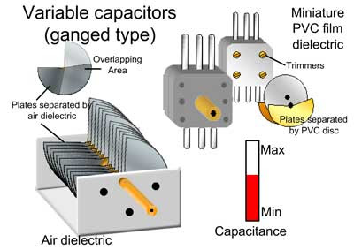
In variable types of capacitors, some arrangement is made to change the area of the plates facing each other. it is generally a combination of many capacitors with air as dielectric. it consist of two sets of plates. One set remains fixed while the other set can rotates so the distance between the plates does not charge and they do not touch each other. The common area of the plates of the two sets which faces each other, determinant the value of capacitance. Thus, the capacitance of the capacitor can be increased or to be decreased by turning the rotate able plates in or out of the space between the static plates. Such types of capacitors are utilized for tuning into radio sets.


An electrolytic capacitor is often used to store large amount of charge at relative low voltages. it consist of metal foil in contact with electrolyte-a solution that conduct charge by virtue of the motion of the ions contained in it. When the voltages are applied between the foil and the electrolyte, a thin layer of metal oxide is formed on the foil , and this layer is served as the dielectric. Very large capacitance can be attained because the dielectric layer is very thin.

Uses Of Capacitors

Capacitor have a wide range of application in different electric and electronic circuits. For example, they are used or tuning transmitter, receives and transistor radios. They are also used for table fans, exhaust fan, fan motors in air conditioners coolers, motors washing machines, air conditioners and many other appliances for their smooth working.  Capacitors are also used in electronic circuits of computers e.t.c 

Capacitors are likewise utilized as a part of electronic circuits of PCs e.t.c Capacitor can likewise be utilized to separate between high recurrence and low recurrence signals which make them valuable in electronic circuits. For example, capacitor are used in the resonate circuit that tune radios to particular frequencies. Such circuits are called filter circuits. One sort of capacitor may not be reasonable for all applications. Ceramic capacitor are generally superior to other types and therefore can be used in vast ranges of applications.

Monday 13 March 2017

Refraction Of Light | Laws Of Refraction | Speed Of Light In A Medium | Refractive Index

Refraction Of Light

   If we dip of one end of pencil or other object into water at an angle to the surface, the submerged part looks bent as shown below. It's image is displaced because the light coming from the under water portion of the object changes direction as it leaves the water. This bending of light as it passes from one transparent medium into another is called refraction
refraction

As we can see the Reflection Of Light now we discussed about the refraction of light. Refraction of light can be explained with the help of fig that is shown bellow. A ray of light IO traveling from air falls on the surface of glass block. At the air glass interfaces, the ray of light changes direction and bends towards the normal and travel along the path OR inside the glass block.The ray IO and OR inside are called the incident ray and the refracted ray respectively. The angle "i" made by the incident ray with the normal is called angle of incident. The angle "r" made by the refracted ray with the normal is called angle of refraction. When refracted ray leave the glass, it bends away from the normal and travel along the path ME. Thus

The process of bending of light as it passes from air into glass and ice versa is called refraction of light.


 Laws Of Refraction

 (i) The incident ray, the refracted ray, and the normal at the point of incidence all lie in the same plane.
(ii) The ratio of the sign of the angle of incidence "i"  to the sine of the angle of refraction "r" is always equal to a constant i.e., sin i / sin r = constant = n

Where the ratio sin i / sin r is known as the refractive index of the second medium with respect to the first medium. So we have  sin i / sin r = n

Speed Of Light In A Medium

 Refraction of light is caused by the difference in speed of light in different media. For example, the speed of light in air is approximated 3.0 *10^8 m/s. However, when light travels through the medium, such as water or glass, it's speed decrees. The speed of light in water is approximately 2.3 * 10^8 m/s, while in glass, it is approximately 2.0*10^8 m/s. To described the changes in the speed of light in a medium, we use the term index of refraction or refractive index.


Refractive Index 

The refracted index "n" of a medium is the ratio of the speed of light "c" in air to the speed "v" of light in the medium.

  Refractive Index = Speed of light in air / Speed of light in medium 
      Or
                         n = c / v

Sunday 12 March 2017

Reflection Of Light | Laws of Reflection | Types of Reflection

Reflection Of Light


Reflection of light is illustrated in bellow Fig. At the point when a beam of light from air along the way AO falls on a plane mirror M, it is avoided along the way OB.. The ray AO is called incident ray while the ray OB is called reflected ray. The angle between incident ray AO and normal N, i.e, <AON is called the angle of incident represented by i. The angle between reflected ray OB, i.e, < NOB is called the angle of reflection represented by r.
Fig. 1
Now we can define the phenomenon of reflection as:
  When light in a certain medium falls on the surface of another medium, a part of it turn back in the same medium.
Laws of Reflection
 (i) The incident ray, the normal, and the reflected ray at the point of incidence all lie in the same plane.
 (ii) The angle of incidence is equal to the angle of reflection i.e., i=r


Types of Reflection
 Nature of reflection depends on smoothness of surface. For example, a smooth surface of sliver reflects rays of light in one direction only. The reflection by these smooth surfaces is called Regular Reflection. Most of the object in everyday world are not smooth on the microscopic level. The rough surface of the objects reflect the rays of light in many directions. Such type of reflection is called diffuse reflection. Regular reflection and diffuse reflection both are shown bellow.